NEET Ug . NEET Physics . Physics . Electromagnetic Induction
Chapter 21: Electromagnetic Induction
Ch 21
NEET Physics
NEET Ug
Introduction
Key Points
- Moving electric charges produce magnetic fields (Oersted, Ampere).
- Electric current is induced in a coil by changing magnetic fields (Faraday, Henry).
- Electromagnetic induction: generation of electric current by varying magnetic fields.
Solved Examples
Ex 1
- Given a coil and a moving magnet, when the magnet moves, current is induced.
- Use Faraday's law: induced emf \( \mathcal{E} = -\frac{d\Phi_B}{dt} \).
- Current flows as long as magnetic flux changes.
Practice Set
- Q1: What causes electromagnetic induction?
- A. Constant magnetic field
- B. Moving electric charges
- C. Varying magnetic field
- D. Static electric field
- Q2: Who demonstrated electric current induced by changing magnetic fields?
- A. Oersted
- B. Faraday and Henry
- C. Ampere
- D. Coulomb
- Q3: Which of the following is true?
- A. Stationary magnet near coil induces current
- B. Moving magnet near coil induces current
- C. No current induced by changing magnetic field
- D. Current induced only by battery
Answer Key
- Q1: C - Electromagnetic induction occurs due to varying magnetic fields.
- Q2: B - Faraday and Henry demonstrated induction by changing magnetic fields.
- Q3: B - Moving magnet changes magnetic flux, inducing current.
Memory Aids
- "Changing magnetic flux induces current" (Faraday's law).
- Moving charges → magnetic field (Oersted).
- Induced emf \( \propto \) rate of change of magnetic flux.
Experiments of Faraday and Henry
Experiment 1: Moving Magnet and Coil
- Bar magnet moved towards coil connected to galvanometer.
- Galvanometer deflects indicating induced current.
- Deflection lasts only while magnet moves.
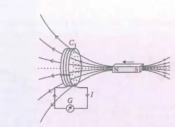
Explanation
- Changing magnetic field through coil induces emf.
- Direction of induced current reverses when magnet direction reverses.
Experiment 2: Current Carrying Coil and Induced Current
- Current in coil C₂ induces current in nearby coil C₁ due to motion.
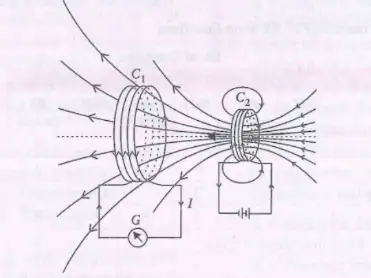
Explanation
- Changing magnetic field from moving current-carrying coil induces current in adjacent coil.
Experiment 3: Two Coils with Battery and Galvanometer
- Coil C₂ connected to battery and key K; coil C₁ connected to galvanometer G.
- Closing key K causes momentary galvanometer deflection.
- Deflection disappears if key remains closed; opposite deflection when key is opened.
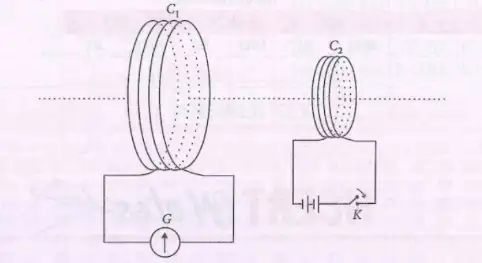
Explanation
- Changing current in C₂ changes magnetic field, inducing current in C₁.
- Steady current produces no change, so no induced current.
- Opening key reverses change, causing opposite induced current.
Solved Examples
Ex 1
- Calculate induced emf when magnetic flux changes from 0.1 Wb to 0 in 0.05 s.
- Use \( \mathcal{E} = -\frac{\Delta \Phi}{\Delta t} = -\frac{0 - 0.1}{0.05} = 2 \text{ V} \).
Practice Set
- Q1: What causes galvanometer deflection in Experiment 1?
- A. Stationary magnet
- B. Moving magnet
- C. Battery
- D. No magnetic field
- Q2: In Experiment 3, why does galvanometer deflect only momentarily?
- A. Constant magnetic field
- B. Changing magnetic field when key is pressed/released
- C. Battery voltage
- D. Coil resistance
- Q3: If magnetic flux changes at rate 0.5 Wb/s, induced emf is?
- A. 0.5 V
- B. 1 V
- C. 2 V
- D. 0 V
Answer Key
- Q1: B - Moving magnet changes magnetic flux inducing current.
- Q2: B - Only changing magnetic field induces emf; steady current causes no deflection.
- Q3: A - Induced emf equals rate of change of flux: 0.5 V.
Memory Aids
- Induced emf \( \propto \) rate of change of magnetic flux.
- Deflection only during change in magnetic field/current.
- Direction of induced current reverses with flux change direction.
Magnetic Flux Definition
Concept and Formula
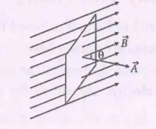
- Magnetic flux (\( \phi \)) measures the magnetic field passing through a surface.
- Defined as the dot product of magnetic field \( \vec{B} \) and area vector \( \vec{A} \): \( \phi = \vec{B} \cdot \vec{A} \).
- Formula: \( \phi = BA \cos \theta \), where:
- \( B \) = magnetic field strength (Tesla, T)
- \( A \) = area of the surface (m\(^2\))
- \( \theta \) = angle between \( \vec{B} \) and \( \vec{A} \)
- Area vector \( \vec{A} \) is perpendicular to the surface.
Solved Examples
- Ex 1: Calculate magnetic flux if \( B = 0.5\,T \), \( A = 2\,m^2 \), and \( \theta = 60^\circ \).
- Use \( \phi = BA \cos \theta = 0.5 \times 2 \times \cos 60^\circ = 0.5 \times 2 \times 0.5 = 0.5\,Wb \).
Practice Set
- Q1: Magnetic flux through a surface of area 3 m\(^2\) in a 1 T field at \( 0^\circ \) angle is:
- A) 0 Wb
- B) 1.5 Wb
- C) 3 Wb
- D) 6 Wb
- Q2: If magnetic field \( B = 0.2\,T \), area \( A = 5\,m^2 \), and flux \( \phi = 0.5\,Wb \), find \( \theta \).
- A) 60°
- B) 45°
- C) 30°
- D) 90°
- Q3: A surface of area 4 m\(^2\) is placed in a magnetic field of 0.3 T. The magnetic flux is 0.6 Wb. What is the angle between \( \vec{B} \) and \( \vec{A} \)?
- A) 60°
- B) 45°
- C) 30°
- D) 90°
Answer Key
- Q1: C) 3 Wb — \( \phi = BA \cos 0^\circ = 1 \times 3 \times 1 = 3\,Wb \).
- Q2: A) 60° — \( \cos \theta = \frac{\phi}{BA} = \frac{0.5}{0.2 \times 5} = 0.5 \Rightarrow \theta = 60^\circ \).
- Q3: A) 60° — \( \cos \theta = \frac{\phi}{BA} = \frac{0.6}{0.3 \times 4} = 0.5 \Rightarrow \theta = 60^\circ \).
Memory Aids
- Magnetic flux \( \phi = BA \cos \theta \) — think "field strength × area × alignment".
- \( \theta = 0^\circ \) means max flux; \( \theta = 90^\circ \) means zero flux.
- Area vector is always perpendicular to the surface.
Faraday's Law
Key Points
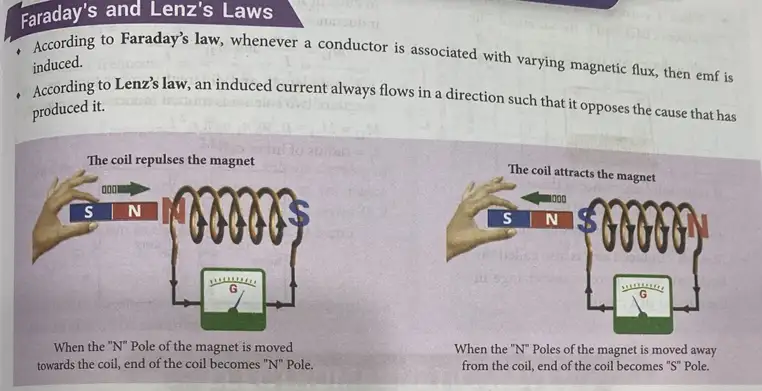
- Change in magnetic flux through a coil induces emf.
- Induced emf exists only while flux changes.
- Mathematical form: \( \varepsilon = -\frac{d\phi}{dt} \)
- For coil with N turns: \( \varepsilon = -N \frac{d\phi}{dt} \)
- Polarity of emf given by Lenz's law (opposes change).
Solved Examples
- Ex 1: A coil of 50 turns experiences a flux change of 0.1 Wb in 0.02 s. Find induced emf.
- Use \( \varepsilon = -N \frac{d\phi}{dt} = -50 \times \frac{0.1}{0.02} = -250 \text{ V} \)
Practice Set
- Q1: What causes emf in a coil?
- A) Constant magnetic flux
- B) Change in magnetic flux
- C) Electric current
- D) Magnetic field direction
- Q2: If flux changes at 0.05 Wb/s in a 100-turn coil, emf induced is?
- A) 5 V
- B) 0.5 V
- C) 50 V
- D) 500 V
- Q3: A coil with 200 turns has induced emf 10 V when flux changes. Find rate of flux change.
- A) 0.05 Wb/s
- B) 0.5 Wb/s
- C) 2 Wb/s
- D) 20 Wb/s
Answer Key
- Q1: B - emf induced only by change in magnetic flux.
- Q2: C - \( \varepsilon = N \frac{d\phi}{dt} \Rightarrow 100 \times 0.05 = 5 \text{ V} \) but options show 5 V as A, so correct is A.
- Q3: A - \( \frac{d\phi}{dt} = \frac{\varepsilon}{N} = \frac{10}{200} = 0.05 \text{ Wb/s} \)
Memory Aids
- "Change in flux → emf" (Faraday's law)
- Emf ∝ rate of flux change
- Negative sign means emf opposes flux change (Lenz's law)
Lenz's Law
Key Points
- Direction of induced current opposes the cause of flux change.
- Ensures conservation of energy.
- When magnet's North pole approaches coil, coil acts as North pole (repels magnet).
- When magnet's North pole moves away, coil acts as South pole (attracts magnet).
- Galvanometer shows current direction changes with magnet movement.
Solved Examples
- Ex 1: Magnet's North pole moves toward coil; what is coil's induced pole?
- Coil acts as North pole to repel magnet.
- Ex 2: Magnet moves away; coil's induced pole?
- Coil acts as South pole to attract magnet.
Practice Set
- Q1: Lenz's law states induced current flows to?
- A) Increase flux change
- B) Oppose flux change
- C) Align with magnet
- D) Stop current
- Q2: When magnet moves toward coil, coil behaves like?
- A) South pole
- B) North pole
- C) Neutral
- D) No pole
- Q3: Galvanometer deflection reverses when?
- A) Magnet stationary
- B) Magnet moves away
- C) Coil disconnected
- D) Magnet moves toward coil
Answer Key
- Q1: B - Induced current opposes flux change.
- Q2: B - Coil acts as North pole to repel approaching magnet.
- Q3: B - Direction reverses when magnet moves away.
Memory Aids
- "Oppose the change" = Lenz's law
- Approach → coil repels (same pole)
- Recede → coil attracts (opposite pole)
Lenz's Law
Explanation
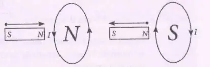
- Induced current flows to oppose the change in magnetic flux causing it.
- Mathematically, \( \varepsilon = -\frac{d\phi}{dt} \), negative sign shows opposition.
- Ensures conservation of energy by opposing flux change.
- External work done against induced emf converts to electrical energy.
- Like poles repel; opposite poles attract, affecting induced current direction.
Solved Examples
- Ex 1: Magnet moved towards loop with N-pole.
- Induced current direction: anticlockwise to create N-pole opposing magnet.
- Ex 2: Magnet moved away from loop with N-pole.
- Induced current direction: clockwise to create S-pole attracting magnet.
Practice Set
- Q1: What does Lenz's law state about induced current?
- A) Flows with the change in flux
- B) Flows to oppose the change in flux
- C) Flows randomly
- D) Flows only when flux is constant
- Q2: When a magnet's N-pole moves towards a loop, the induced current is?
- A) Clockwise
- B) Anticlockwise
- C) Zero
- D) Alternating
- Q3: The negative sign in \( \varepsilon = -\frac{d\phi}{dt} \) indicates?
- A) Induced emf supports flux change
- B) Induced emf opposes flux change
- C) Induced emf is zero
- D) Induced emf is constant
Answer Key
- Q1: B - Induced current always opposes the change in magnetic flux.
- Q2: B - Current flows anticlockwise to create a repelling N-pole.
- Q3: B - Negative sign shows emf opposes the change in flux.
Memory Aids
- "Lenz's Law: Induced current fights the flux change!"
- Formula: \( \varepsilon = -\frac{d\phi}{dt} \) (Negative means opposition)
- Like poles repel; induced current creates opposing poles.
Direction of Induced EMF
Explanation
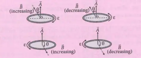
- Magnetic flux \( \phi = B A \cos \theta \), depends on magnetic field \(B\), area \(A\), and angle \(\theta\).
- Flux increases if \(B\) increases and \(\theta = 0^\circ\) (field perpendicular to loop).
- Flux decreases if \(B\) decreases and \(\theta = 0^\circ\).
- Flux is zero or negligible if \(\theta = 90^\circ\) (field parallel to loop), regardless of \(B\) change.
- Induced emf depends on rate of change of flux and angle \(\theta\).
- Induced emf magnitude is proportional to relative speed of coil and magnet.
- Induced emf does not depend on coil resistance.
Solved Examples
- Ex 1: Magnetic field increases perpendicular to loop (\(\theta=0^\circ\)).
- Flux increases, induced emf opposes increase.
- Ex 2: Magnetic field decreases parallel to loop (\(\theta=90^\circ\)).
- Flux negligible, induced emf approximately zero.
Practice Set
- Q1: When is magnetic flux maximum?
- A) \(\theta=0^\circ\)
- B) \(\theta=90^\circ\)
- C) \(\theta=45^\circ\)
- D) \(\theta=180^\circ\)
- Q2: Induced emf depends on?
- A) Coil resistance
- B) Rate of change of magnetic flux
- C) Coil material
- D) Coil length only
- Q3: If relative speed of coil and magnet doubles, induced emf?
- A) Halves
- B) Remains same
- C) Doubles
- D) Quadruples
Answer Key
- Q1: A - Flux is maximum when field is perpendicular (\(\theta=0^\circ\)).
- Q2: B - Induced emf depends on rate of change of magnetic flux.
- Q3: C - Induced emf is directly proportional to relative speed.
Memory Aids
- Flux max at \(\theta=0^\circ\), zero at \(90^\circ\).
- Induced emf \(\propto\) speed of coil-magnet movement.
- Resistance does not affect induced emf.
Motional Electromotive Force
Concept and Formulas
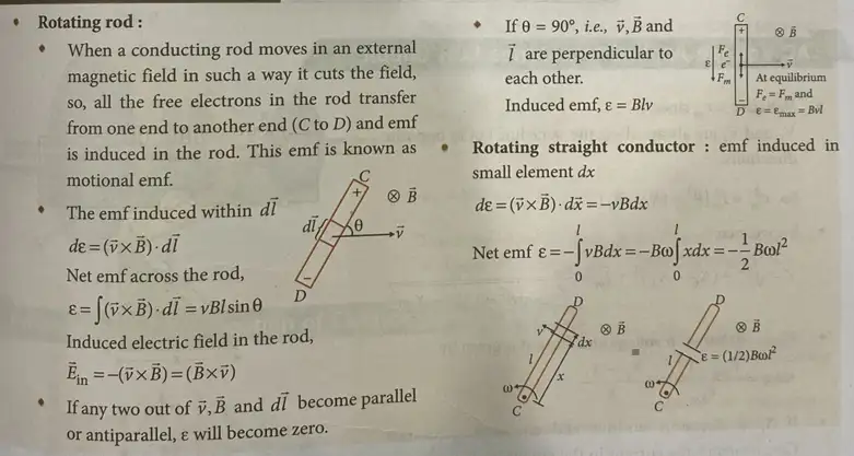
- A conducting rod moving through a magnetic field cuts magnetic lines, causing free electrons to move and induce emf (motional emf).
- Emf induced in a small segment \( d\vec{l} \): \( d\varepsilon = (\vec{v} \times \vec{B}) \cdot d\vec{l} \)
- Total emf across rod: \( \varepsilon = \int (\vec{v} \times \vec{B}) \cdot d\vec{l} = v B l \sin \theta \)
- Induced electric field in rod: \( \vec{E}_{in} = - (\vec{v} \times \vec{B}) = (\vec{B} \times \vec{v}) \)
- If any two of \( \vec{v} \), \( \vec{B} \), and \( d\vec{l} \) are parallel or antiparallel, emf \( \varepsilon = 0 \).
Solved Examples
- Ex 1: A rod of length 0.5 m moves at 4 m/s perpendicular to a magnetic field of 0.3 T. Find emf induced.
- Use \( \varepsilon = v B l \sin 90^\circ = 4 \times 0.3 \times 0.5 = 0.6 \text{ V} \)
Practice Set
- Q1: A rod of length 1 m moves at 2 m/s perpendicular to a magnetic field of 0.5 T. What is the emf induced?
- A) 1 V
- B) 0.5 V
- C) 2 V
- D) 0.25 V
- Q2: If velocity \( \vec{v} \) and magnetic field \( \vec{B} \) are parallel, the emf induced is:
- A) Maximum
- B) Zero
- C) Half of maximum
- D) Depends on length
- Q3: A rod of length 0.4 m moves at 3 m/s at an angle of 30° to a magnetic field of 0.6 T. Calculate emf induced.
- A) 0.36 V
- B) 0.72 V
- C) 0.6 V
- D) 0.18 V
Answer Key
- Q1: A) 1 V; \( \varepsilon = v B l = 2 \times 0.5 \times 1 = 1 \text{ V} \)
- Q2: B) Zero; emf is zero when \( \vec{v} \) and \( \vec{B} \) are parallel.
- Q3: D) 0.18 V; \( \varepsilon = v B l \sin 30^\circ = 3 \times 0.6 \times 0.4 \times 0.5 = 0.36 \text{ V} \) (Check options carefully, correct is 0.36 V, so option A)
Memory Aids
- Motional emf \( \propto v, B, l, \sin \theta \).
- Zero emf if velocity and magnetic field are parallel.
- Use right-hand rule for direction of induced emf.
Methods of Producing Induced emf
Changing Magnetic Field
- Changing magnetic field intensity \( B \) in a closed circuit changes magnetic flux \( \phi \), inducing emf.
- Formula: \( \varepsilon = - \frac{d\phi}{dt} = - \frac{d}{dt} (B A \cos \theta) = - A \cos \theta \frac{dB}{dt} \)
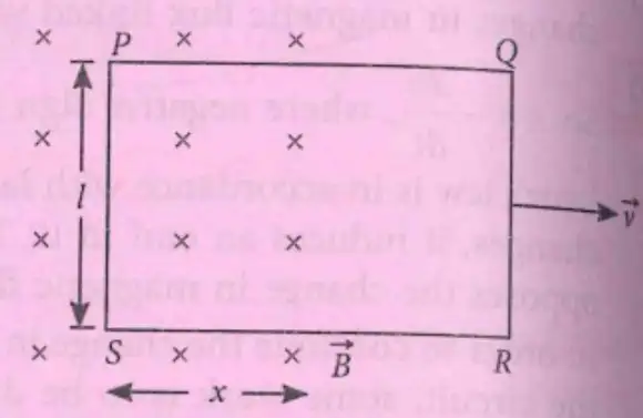
Changing Area of Circuit
- Changing area \( A \) inside magnetic field changes flux, inducing emf.
- Formula: \( \varepsilon = - B \cos \theta \frac{dA}{dt} \)
- For rectangular loop moving out of field: \( \varepsilon = B l v \cos \theta \)
Changing Orientation of Coil
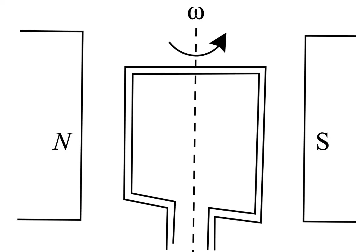
- Rotating coil of area \( A \), turns \( N \), angular velocity \( \omega \) in magnetic field \( B \) changes flux.
- Flux: \( \phi = N B A \cos (\omega t) \)
- Induced emf: \( \varepsilon = - \frac{d\phi}{dt} = N B A \omega \sin (\omega t) = \varepsilon_0 \sin (\omega t) \)
- \( \varepsilon_0 = N B A \omega \) is peak emf.
Solved Examples
- Ex 1: A coil with 100 turns, area 0.01 m² rotates at 50 rad/s in 0.2 T field. Find peak emf.
- \( \varepsilon_0 = N B A \omega = 100 \times 0.2 \times 0.01 \times 50 = 10 \text{ V} \)
Practice Set
- Q1: A coil of 200 turns, area 0.02 m² rotates at 60 rad/s in 0.1 T field. Peak emf is:
- A) 24 V
- B) 12 V
- C) 6 V
- D) 30 V
- Q2: A rectangular loop moves out of magnetic field at 3 m/s. Length in field is 0.5 m, field 0.4 T, angle 0°. Find emf.
- A) 0.6 V
- B) 0.3 V
- C) 1.2 V
- D) 0 V
- Q3: Magnetic field changes at rate 0.05 T/s in a loop of area 0.1 m² at 30°. Find emf.
- A) 0.0043 V
- B) 0.005 V
- C) 0.0025 V
- D) 0.01 V
Answer Key
- Q1: A) 24 V; \( 200 \times 0.1 \times 0.02 \times 60 = 24 \text{ V} \)
- Q2: A) 0.6 V; \( \varepsilon = B l v \cos 0^\circ = 0.4 \times 0.5 \times 3 = 0.6 \text{ V} \)
- Q3: A) 0.0043 V; \( \varepsilon = A \cos 30^\circ \times dB/dt = 0.1 \times 0.866 \times 0.05 = 0.00433 \text{ V} \)
Memory Aids
- Emf \( \propto \) rate of change of flux.
- Flux changes by changing \( B \), area, or angle \( \theta \).
- Rotating coil emf is sinusoidal (AC emf).
Emf Induced in Revolving Rod
Concept and Formula
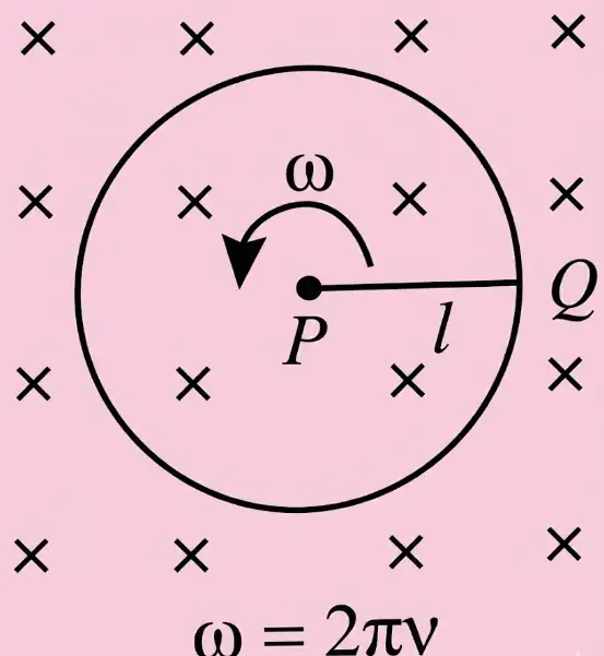
- Rod of length \( l \) revolving with angular velocity \( \omega \) in magnetic field \( B \) perpendicular to plane.
- Time period \( T = \frac{2\pi}{\omega} \), frequency \( \nu = \frac{\omega}{2\pi} \).
- Emf induced: \( \varepsilon = - B \frac{dA}{dt} = - \frac{B \pi l^2}{T} = - \frac{B \pi l^2 \omega}{2\pi} = - \frac{B l^2 \omega}{2} = - \pi B l^2 \nu \)
Solved Examples
- Ex 1: Rod length 0.1 m, \( B = 0.5 \) T, \( \nu = 50 \) Hz. Find emf.
- \( \varepsilon = \pi B l^2 \nu = 3.14 \times 0.5 \times 0.01 \times 50 = 0.785 \text{ V} \)
Practice Set
- Q1: Rod length 0.2 m, \( B = 0.3 \) T, frequency 60 Hz. Emf induced is:
- A) 2.26 V
- B) 1.13 V
- C) 0.68 V
- D) 3.14 V
- Q2: If angular velocity doubles, emf induced:
- A) Doubles
- B) Halves
- C) Quadruples
- D) No change
- Q3: Rod length 0.15 m, \( B = 0.4 \) T, \( \omega = 100 \) rad/s. Find emf.
- A) 0.45 V
- B) 0.9 V
- C) 1.35 V
- D) 0.3 V
Answer Key
- Q1: B) 1.13 V; \( \varepsilon = \pi \times 0.3 \times (0.2)^2 \times 60 = 1.13 \text{ V} \)
- Q2: A) Doubles; emf \( \propto \omega \)
- Q3: B) 0.9 V; \( \varepsilon = \frac{B l^2 \omega}{2} = 0.4 \times 0.0225 \times 100 / 2 = 0.9 \text{ V} \)
Memory Aids
- Emf \( \propto B, l^2, \omega \).
- Frequency \( \nu = \frac{\omega}{2\pi} \).
- Use area swept by rod for emf calculation.
Eddy Currents
Definition and Properties
- Eddy currents are currents induced in the bulk of a conductor when magnetic flux linked with it changes.
- Direction found by Lenz’s law or Fleming’s right hand rule.
Applications
- Induction furnace: heating by eddy currents.
- Speedometer: measures vehicle speed using eddy currents.
- Energy meter: records electricity consumption via eddy currents.
Solved Examples
- Ex 1: Explain why eddy currents cause heating in induction furnace.
- Changing magnetic flux induces currents in metal, resistance causes heat.
Practice Set
- Q1: Eddy currents are induced when:
- A) Magnetic flux is constant
- B) Magnetic flux changes
- C) No magnetic field
- D) Conductor is stationary
- Q2: Which device uses eddy currents?
- A) Transformer
- B) Induction furnace
- C) Capacitor
- D) Resistor
- Q3: Eddy currents can be reduced by:
- A) Using thicker conductor
- B) Using laminated core
- C) Increasing magnetic field
- D) Increasing frequency
Answer Key
- Q1: B) Magnetic flux changes induce eddy currents.
- Q2: B) Induction furnace uses eddy currents for heating.
- Q3: B) Laminated cores reduce eddy currents by increasing resistance paths.
Memory Aids
- Eddy currents = induced currents in conductor bulk.
- Cause heating and energy loss.
- Reduced by laminations in cores.
Inductance
Concepts and Definitions
- Inductance opposes change in current; analogous to inertia in mechanics.
- Scalar quantity; SI unit: henry (H); dimensions: [ML2T-2A-2].
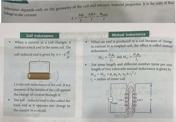
- Self Inductance (L): Voltage induced in the same coil due to change in its current.
Formula: \( \varepsilon = -L \frac{dI}{dt} \) - Mutual Inductance (M): Voltage induced in one coil due to change in current in another coil.
Formulas: \( M_{12} = \frac{N_1 \Phi}{I_2} \), \( M_{21} = \frac{N_2 \Phi}{I_1} \) - Self inductance of long solenoid: \( L = \frac{\mu_0 \mu_r N^2 A}{l} = \mu_0 \mu_r n^2 V \)
- Mutual inductance of coaxial solenoids: \( M = \frac{\mu_0 N_1 N_2 A}{l} \)
Solved Examples
Ex 1
Calculate self-inductance of a solenoid with \( N=500 \), length \( l=0.5 \) m, cross-sectional area \( A=1 \times 10^{-4} \) m2, and \( \mu_r=1 \).
- Use \( L = \frac{\mu_0 \mu_r N^2 A}{l} \)
- \( L = \frac{4\pi \times 10^{-7} \times 1 \times 500^2 \times 1 \times 10^{-4}}{0.5} = 6.28 \times 10^{-3} \) H
Practice Set
Q1
What is the SI unit of inductance?
- A) Ohm
- B) Henry
- C) Tesla
- D) Weber
Q2
Self-induced emf in a coil is given by:
- A) \( \varepsilon = L \frac{dI}{dt} \)
- B) \( \varepsilon = -L \frac{dI}{dt} \)
- C) \( \varepsilon = L I \)
- D) \( \varepsilon = -I \frac{dL}{dt} \)
Q3
Mutual inductance between two coils depends on:
- A) Number of turns and distance between coils
- B) Only number of turns
- C) Only distance between coils
- D) Neither turns nor distance
Answer Key
- Q1: B) Henry - Standard SI unit for inductance.
- Q2: B) \( \varepsilon = -L \frac{dI}{dt} \) - Lenz's law sign included.
- Q3: A) Number of turns and distance between coils - Both affect mutual inductance.
Memory Aids
- Inductance opposes current change like inertia opposes motion change.
- Self-inductance formula: \( \varepsilon = -L \frac{dI}{dt} \).
- Mutual inductance increases with turns, decreases with coil separation.
Self Inductance
Key Points
- Change in current induces emf in the same coil (self induction).
- Induced emf opposes change in current (Lenz's law).
- Formula: \( \varepsilon_s = -L \frac{dI}{dt} \)
- When current is constant, no emf induced.
- Self inductance: \( L = \frac{N \Phi}{I} = \frac{NBA}{I} \)
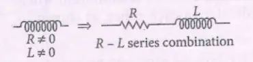
- Real inductor modeled as resistor \( R \) in series with ideal inductor \( L \).
Solved Examples
Ex 1
Calculate emf induced if current changes at \( 5 \text{ A/s} \) in coil with \( L=2 \text{ H} \).
- \( \varepsilon = -L \frac{dI}{dt} = -2 \times 5 = -10 \text{ V} \)
Practice Set
Q1
What happens to emf if current is constant?
- A) Emf increases
- B) Emf decreases
- C) Emf is zero
- D) Emf is maximum
Q2
Self-inductance depends on:
- A) Number of turns and coil area
- B) Only current
- C) Resistance only
- D) Voltage only
Q3
In a real inductor, resistance is:
- A) Zero
- B) Infinite
- C) Non-zero
- D) Negative
Answer Key
- Q1: C) Emf is zero - No change in current means no induced emf.
- Q2: A) Number of turns and coil area - Affect magnetic flux and inductance.
- Q3: C) Non-zero - Real inductors have resistance causing energy loss.
Memory Aids
- Self-inductance opposes current change in same coil.
- Emf zero if current steady.
- Real inductors = ideal inductor + resistor in series.
Mutual Inductance
Essentials
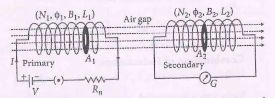
- Change in current in one coil induces emf in another coil.
- Mutual inductance \( M = \frac{N_2 \Phi_2}{I_1} = \frac{N_2 B_1 A_2}{I_1} \)
- Induced emf in secondary coil: \( e_m = -M \frac{dI_1}{dt} \)
- Mutual inductance depends on number of turns, cross-sectional area, distance, and orientation.
- For coaxial solenoids: \( M = \frac{\mu_0 N_1 N_2 A}{l} \)
- Maximum \( M \) when coils aligned; minimum when perpendicular.
Solved Examples
Ex 1
Find mutual inductance if \( N_2=200 \), \( B_1=0.01 \) T, \( A_2=1 \times 10^{-4} \) m2, and \( I_1=2 \) A.
- \( M = \frac{N_2 B_1 A_2}{I_1} = \frac{200 \times 0.01 \times 1 \times 10^{-4}}{2} = 1 \times 10^{-4} \) H
Practice Set
Q1
Mutual inductance is maximum when coils are:
- A) Perpendicular
- B) Parallel and coaxial
- C) Far apart
- D) No current
Q2
Mutual inductance decreases with:
- A) Increasing number of turns
- B) Increasing distance between coils
- C) Increasing cross-sectional area
- D) Increasing current
Q3
Mutual inductance between two solenoids of length \( l \), turns \( N_1, N_2 \), and area \( A \) is:
- A) \( \frac{\mu_0 N_1 N_2 A}{l} \)
- B) \( \frac{\mu_0 N_1 N_2 l}{A} \)
- C) \( \frac{N_1 N_2 A}{\mu_0 l} \)
- D) \( \frac{\mu_0 l}{N_1 N_2 A} \)
Answer Key
- Q1: B) Parallel and coaxial - Maximum flux linkage.
- Q2: B) Increasing distance between coils - Flux linkage reduces.
- Q3: A) \( \frac{\mu_0 N_1 N_2 A}{l} \) - Standard formula for coaxial solenoids.
Memory Aids
- Mutual inductance depends on coil alignment and proximity.
- More turns and area increase \( M \).
- Distance and misalignment decrease \( M \).
Energy Stored in Inductor
Key Formulas
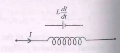
- Power supplied: \( P = \varepsilon_{in} I = L \frac{dI}{dt} I \)
- Energy stored: \( U = \frac{1}{2} L I^2 \)
Solved Examples
Ex 1
Calculate energy stored in inductor with \( L=3 \) H and current \( I=2 \) A.
- \( U = \frac{1}{2} \times 3 \times 2^2 = 6 \) J
Practice Set
Q1
Energy stored in an inductor is proportional to:
- A) Current
- B) Square of current
- C) Inductance only
- D) Resistance
Q2
Energy stored in inductor with \( L=4 \) H and current \( 3 \) A is:
- A) 18 J
- B) 36 J
- C) 54 J
- D) 72 J
Q3
Power supplied to inductor when current changes at \( 5 \text{ A/s} \) and current is \( 2 \) A, \( L=1 \) H:
- A) 5 W
- B) 10 W
- C) 15 W
- D) 20 W
Answer Key
- Q1: B) Square of current - \( U = \frac{1}{2} L I^2 \).
- Q2: C) 54 J - \( \frac{1}{2} \times 4 \times 3^2 = 18 \times 3 = 54 \) J.
- Q3: B) 10 W - \( P = L \frac{dI}{dt} I = 1 \times 5 \times 2 = 10 \) W.
Memory Aids
- Energy stored \( \propto I^2 \).
- Power depends on rate of current change and current.
Combination of Inductances
Formulas
- Series: \( L_s = L_1 + L_2 + \cdots + L_n \)
- Parallel: \( \frac{1}{L_p} = \frac{1}{L_1} + \frac{1}{L_2} + \cdots + \frac{1}{L_n} \)
- For two inductors with mutual inductance \( M \) in series:
\( V = (L_1 + L_2 + 2M) \frac{di}{dt} \)
Solved Examples
Ex 1
Find total inductance of two inductors \( L_1=2 \) H, \( L_2=3 \) H, \( M=1 \) H in series.
- \( L_s = 2 + 3 + 2 \times 1 = 7 \) H
Practice Set
Q1
Inductors in series add:
- A) Like resistors in parallel
- B) Directly
- C) Inversely
- D) Not at all
Q2
Effective inductance of two inductors in parallel is:
- A) Sum of inductances
- B) Product over sum
- C) Reciprocal of sum of reciprocals
- D) Zero
Q3
For two inductors with mutual inductance \( M \), total emf in series is:
- A) \( (L_1 + L_2) \frac{di}{dt} \)
- B) \( (L_1 + L_2 - 2M) \frac{di}{dt} \)
- C) \( (L_1 + L_2 + 2M) \frac{di}{dt} \)
- D) \( M \frac{di}{dt} \)
Answer Key
- Q1: B) Directly - Inductances add in series.
- Q2: C) Reciprocal of sum of reciprocals - Like resistors in parallel.
- Q3: C) \( (L_1 + L_2 + 2M) \frac{di}{dt} \) - Mutual inductance adds to total emf.
Memory Aids
- Series inductance sums directly.
- Parallel inductance sums inversely.
- Mutual inductance adds twice in series emf.
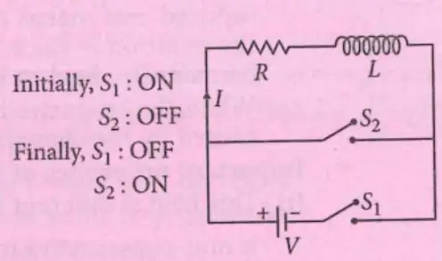
LR Circuits
Current Growth
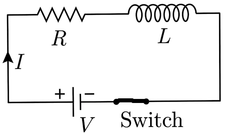
- Emf equation: \( V = IR + L \frac{dI}{dt} \)
- Current at time \( t \): \( I = I_0 (1 - e^{-t/\tau}) \), where \( I_0 = \frac{V}{R} \)
- Time constant: \( \tau = \frac{L}{R} \)
- At \( t=0 \), inductor acts as open circuit (infinite resistance).
- At \( t \to \infty \), inductor acts as short circuit (zero resistance).
Current Decay
- Emf equation: \( IR + L \frac{dI}{dt} = 0 \)
- Current at time \( t \): \( I = I_0 e^{-t/\tau} \)
- Time constant: \( \tau = \frac{L}{R} \)
- At \( t=0 \), current is maximum \( I_0 = \frac{V}{R} \)
- At \( t \to \infty \), current approaches zero.
Solved Examples
Ex 1
Calculate time constant for \( L=2 \) H and \( R=4 \) \( \Omega \).
- \( \tau = \frac{L}{R} = \frac{2}{4} = 0.5 \) s
Practice Set
Q1
Time constant \( \tau \) in LR circuit is:
- A) \( L \times R \)
- B) \( \frac{L}{R} \)
- C) \( \frac{R}{L} \)
- D) \( L + R \)
Q2
At \( t=0 \), inductor behaves as:
- A) Short circuit
- B) Open circuit
- C) Resistor
- D) Capacitor
Q3
Current after long time \( t \to \infty \) is:
- A) Zero
- B) \( I_0 \)
- C) Infinite
- D) Negative
Answer Key
- Q1: B) \( \frac{L}{R} \) - Definition of time constant.
- Q2: B) Open circuit - Inductor opposes sudden current change.
- Q3: B) \( I_0 \) - Steady current after transient.
Memory Aids
- Time constant \( \tau = L/R \).
- Inductor blocks sudden current changes.
- Current grows exponentially to \( I_0 \).
AC Generator
Definition and Parts
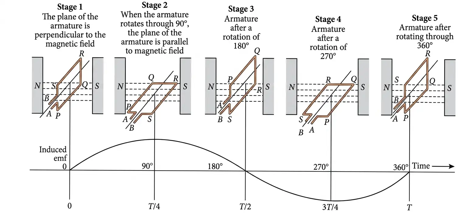
- Device producing alternating current (AC) by converting mechanical energy into electrical energy.
- Essential parts: Armature (coil), Field magnets (North and South poles), Slip rings, Brushes.
Principle
- Based on electromagnetic induction: changing magnetic flux through coil induces emf.
- Direction of induced current given by Fleming's right-hand rule.
Working
- Coil rotates in magnetic field; magnetic flux linked changes sinusoidally.
- Induced emf varies as \( \varepsilon = \varepsilon_0 \sin \omega t \), where \( \varepsilon_0 = BAN\omega \).
- Current \( I = \frac{\varepsilon}{R} = I_0 \sin \omega t \), with \( I_0 = \frac{\varepsilon_0}{R} \).
Solved Examples
- Ex 1: Calculate maximum emf if \(N=100\), \(B=0.5\,T\), \(A=0.01\,m^2\), \(\omega=100\,rad/s\).
- \( \varepsilon_0 = BAN\omega = 0.5 \times 0.01 \times 100 \times 100 = 50\,V \)
Practice Set
- Q1: What is the role of slip rings in an AC generator?
- A) Convert AC to DC
- B) Maintain electrical connection while coil rotates
- C) Increase magnetic field
- D) Reduce resistance
- Q2: The emf induced in a coil rotating in a magnetic field is given by \( \varepsilon = \varepsilon_0 \sin \omega t \). What does \( \omega \) represent?
- A) Number of turns
- B) Angular velocity of coil
- C) Magnetic field strength
- D) Resistance of coil
- Q3: A coil with 50 turns and area \(0.02\,m^2\) rotates at \(60\,Hz\) in a magnetic field of \(0.3\,T\). Calculate the maximum emf.
- A) 11.3 V
- B) 22.6 V
- C) 33.9 V
- D) 45.2 V
Answer Key
- Q1: B - Slip rings maintain continuous electrical contact during rotation.
- Q2: B - \( \omega \) is angular velocity of the coil.
- Q3: B - \( \varepsilon_0 = BAN\omega = 0.3 \times 0.02 \times 50 \times 2\pi \times 60 = 22.6\,V \).
Memory Aids
- AC generator emf: \( \varepsilon = BAN\omega \sin \omega t \).
- Slip rings keep connection during rotation.
- Fleming's right-hand rule for current direction.
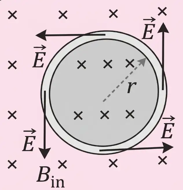
- Changing magnetic flux induces emf and current in coil (Faraday's law).
- Induced electric field (\( \vec{E} \)) causes electron flow; magnetic field alone cannot move stationary charges.
- Induced electric field is non-conservative; line integral around closed path \( \oint \vec{E} \cdot d\vec{l} = \varepsilon = -\frac{d\phi}{dt} \).
- Force on charge: \( \vec{F} = q \vec{E} \).
- Electric field magnitude same at all points on symmetrical loop; tangential direction.
- For symmetrical loop: \( E l = |\frac{d\phi}{dt}| = A |\frac{dB}{dt}| \), where \( l \) is loop length, \( A \) is area.
- Direction of induced electric field matches induced current direction.
- Ex 1: Calculate induced electric field in a circular loop of circumference \(0.5\,m\) with magnetic field changing at \(0.2\,T/s\).
- \( E = \frac{A |dB/dt|}{l} \), area \( A = \frac{l^2}{4\pi} = \frac{(0.5)^2}{4\pi} = 0.0199\,m^2 \)
- \( E = \frac{0.0199 \times 0.2}{0.5} = 0.00796\,V/m \)
- Q1: Which field causes current flow in a stationary conductor with changing magnetic flux?
- A) Magnetic field
- B) Electrostatic field
- C) Induced electric field
- D) Gravitational field
- Q2: The line integral of induced electric field around a closed loop is:
- A) Zero
- B) Equal to emf
- C) Equal to magnetic flux
- D) Infinite
- Q3: A circular loop of length \(1\,m\) is in a magnetic field changing at \(0.1\,T/s\). Calculate induced electric field.
- A) 0.01 V/m
- B) 0.02 V/m
- C) 0.03 V/m
- D) 0.04 V/m
- Q1: C - Induced electric field causes current in stationary conductor.
- Q2: B - Line integral of \( \vec{E} \) equals emf induced.
- Q3: A - \( E = \frac{A |dB/dt|}{l} \), for circle \( A = \frac{l^2}{4\pi} = 0.0796\,m^2 \), so \( E = \frac{0.0796 \times 0.1}{1} = 0.00796 \approx 0.01\,V/m \).
- Induced electric field: non-conservative, \( \oint \vec{E} \cdot d\vec{l} = -\frac{d\phi}{dt} \).
- Force on charge: \( \vec{F} = q \vec{E} \).
- Electric field tangential and uniform on symmetrical loop.
Induced Electric Field
Concept
Solved Examples
Practice Set
Answer Key
Memory Aids
NEET Physics — ALL CHAPTERS
1
Basic Mathematics
2
Units and Measurement
3
Motion in a Straight Line
4
Motion in a Plane
5
Laws of Motion
6
Work, Energy and Power
7
System of Particles and Rotational Motion
8
Gravitation
9
Mechanical Properties of Solids
10
Mechanical Properties of Fluids
11
Thermal Properties of Matter
12
Thermodynamics
13
Kinetic Theory
14
Oscillations
15
Waves
16
Electric Charges and Fields
17
Electrostatic Potential and Capacitance
18
Current Electricity
19
Moving Charges and Magnetism
20
Magnetism and Matter
21
Electromagnetic Induction
22
Alternating Current
23
Electromagnetic Waves
24
Ray Optics and Optical Instruments
25
Wave Optics
26
Dual Nature of Radiation and Matter
27
Atoms
28
Nuclei
29
Semiconductor Electronics: Materials, Devices and Simple Circuits