NEET Ug . NEET Physics . Physics . Alternating Current
Chapter 22: Alternating Current
Ch 22
NEET Physics
NEET Ug
Introduction
Alternating Current (AC) vs Direct Current (DC)
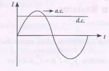
- AC current magnitude changes continuously and reverses direction periodically.
- DC current flows with constant magnitude and fixed direction.
- AC voltage can be efficiently transformed to different voltages using transformers.
Solved Examples
- Ex 1: Identify AC and DC from a graph.
- AC is the sinusoidal wave crossing zero line.
- DC is the constant line above zero.
Practice Set
- Q1: Which current reverses direction periodically?
- A) DC
- B) AC
- C) Both
- D) None
- Q2: Why is AC preferred over DC for power transmission?
- A) AC is safer
- B) AC voltage can be easily transformed
- C) DC is more expensive
- D) DC cannot flow in circuits
- Q3: In the graph, which line represents DC?
- A) Wavy line
- B) Straight line
- C) Both
- D) None
Answer Key
- Q1: B - AC reverses direction periodically.
- Q2: B - AC voltage can be transformed easily using transformers.
- Q3: B - Straight line represents DC current.
Memory Aids
- AC = Alternates direction; DC = Direct flow.
- Transformers work only with AC.
Fundamentals of Alternating Current
AC Current and Voltage Representation
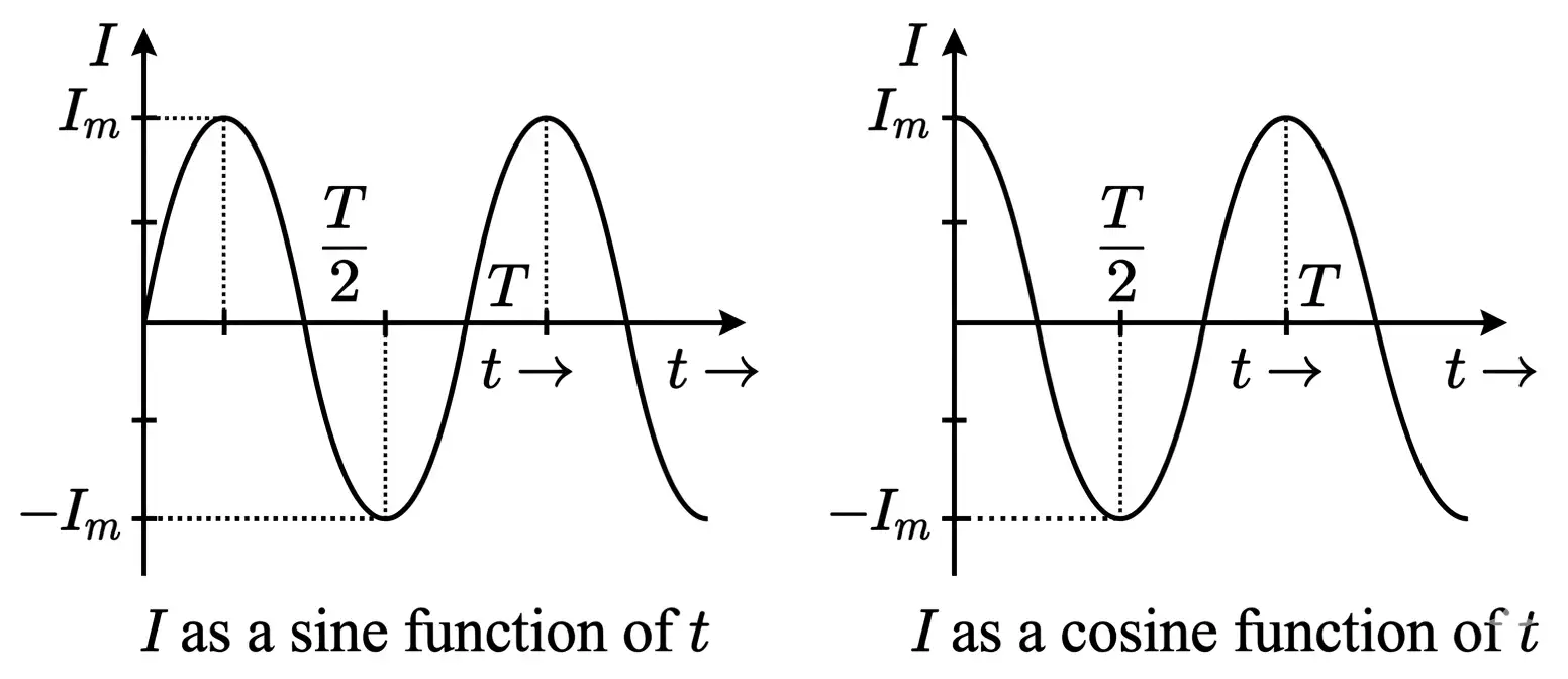
- Instantaneous current: \( I = I_m \sin \omega t \) or \( I = I_m \cos \omega t \)
- \( I_m \): Peak current (amplitude)
- \( \omega = 2\pi / T = 2\pi \nu \): Angular frequency (rad/s)
- \( T \): Time period (s), \( \nu \): Frequency (Hz)
Solved Examples
- Ex 1: Calculate angular frequency if frequency \( \nu = 50 \) Hz.
- \( \omega = 2\pi \times 50 = 314.16 \) rad/s
Practice Set
- Q1: What is the expression for instantaneous current in AC?
- A) \( I = I_m \sin \omega t \)
- B) \( I = I_m \cos \omega t \)
- C) Both A and B
- D) None
- Q2: If \( T = 0.02 \) s, find frequency \( \nu \).
- A) 50 Hz
- B) 20 Hz
- C) 100 Hz
- D) 0.02 Hz
- Q3: Calculate \( \omega \) for \( \nu = 60 \) Hz.
- A) 120 rad/s
- B) 377 rad/s
- C) 60 rad/s
- D) 314 rad/s
Answer Key
- Q1: C - Both sine and cosine represent instantaneous current.
- Q2: A - \( \nu = 1/T = 1/0.02 = 50 \) Hz.
- Q3: B - \( \omega = 2\pi \times 60 = 377 \) rad/s.
Memory Aids
- \( \omega = 2\pi \nu \) always.
- Sine starts at zero; cosine starts at peak.
Average and RMS Values
Definitions and Formulas
- Average value (mean) over half cycle: \( \langle I \rangle = \frac{2 I_m}{\pi} \)
- Root Mean Square (RMS) value: \( I_{rms} = \frac{I_m}{\sqrt{2}} \)
- RMS value equals the DC value producing the same heat in a resistor.
- RMS is also called virtual or apparent value.
Solved Examples
- Ex 1: Find RMS current if \( I_m = 10 \) A.
- \( I_{rms} = 10 / \sqrt{2} = 7.07 \) A
- Ex 2: Calculate average current for half cycle if \( I_m = 10 \) A.
- \( \langle I \rangle = 2 \times 10 / \pi = 6.37 \) A
Practice Set
- Q1: RMS value of current is:
- A) \( I_m \)
- B) \( I_m / 2 \)
- C) \( I_m / \sqrt{2} \)
- D) \( 2 I_m / \pi \)
- Q2: Average current over half cycle is:
- A) \( I_m / 2 \)
- B) \( 2 I_m / \pi \)
- C) \( I_m / \sqrt{2} \)
- D) \( I_m \)
- Q3: If RMS current is 5 A, find peak current \( I_m \).
- A) 3.54 A
- B) 7.07 A
- C) 10 A
- D) 5 A
Answer Key
- Q1: C - RMS current is \( I_m / \sqrt{2} \).
- Q2: B - Average over half cycle is \( 2 I_m / \pi \).
- Q3: B - \( I_m = I_{rms} \times \sqrt{2} = 5 \times 1.414 = 7.07 \) A.
Memory Aids
- Average half cycle = \( 2 I_m / \pi \).
- RMS = peak / \( \sqrt{2} \).
Phase and Phase Difference
Key Concepts
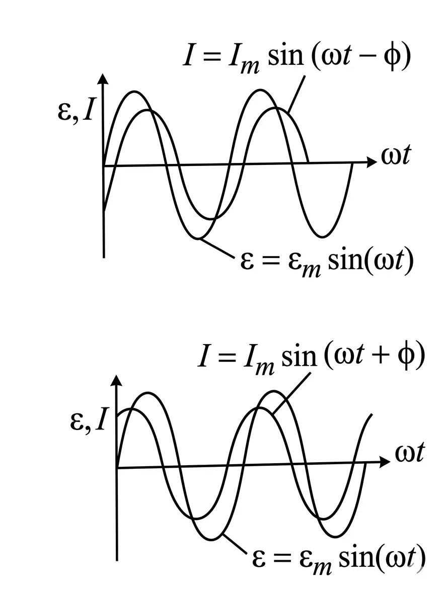
- Current with phase: \( I = I_m \sin (\omega t \pm \phi) \)
- Initial phase \( \phi \) is constant; instantaneous phase \( \omega t \) varies with time.
- Phase difference between voltage \( \varepsilon = \varepsilon_m \sin (\omega t + \phi_1) \) and current \( I = I_m \sin (\omega t + \phi_2) \) is \( \phi = \phi_2 - \phi_1 \).
- Voltage leads current if \( \varepsilon \) reaches max before \( I \) (\( \varepsilon \) leads, \( I \) lags).
- Voltage lags current if \( \varepsilon \) reaches max after \( I \) (\( \varepsilon \) lags, \( I \) leads).
Solved Examples
- Ex 1: If \( \varepsilon = \varepsilon_m \sin \omega t \), and \( I = I_m \sin (\omega t - \phi) \), current lags voltage by \( \phi \).
- Ex 2: If \( \varepsilon = \varepsilon_m \sin (\omega t + \phi) \), and \( I = I_m \sin \omega t \), voltage leads current by \( \phi \).
Practice Set
- Q1: If current lags voltage, phase difference \( \phi \) is:
- A) Positive
- B) Negative
- C) Zero
- D) Undefined
- Q2: Expression for current leading voltage is:
- A) \( I = I_m \sin (\omega t - \phi) \)
- B) \( I = I_m \sin (\omega t + \phi) \)
- C) \( I = I_m \sin \omega t \)
- D) \( I = I_m \cos \omega t \)
- Q3: Phase difference between voltage and current is \( 30^\circ \). If voltage leads, current expression is:
- A) \( I = I_m \sin (\omega t - 30^\circ) \)
- B) \( I = I_m \sin (\omega t + 30^\circ) \)
- C) \( I = I_m \sin \omega t \)
- D) \( I = I_m \cos (\omega t + 30^\circ) \)
Answer Key
- Q1: A - Current lags voltage means positive phase difference.
- Q2: B - Current leading voltage: \( I = I_m \sin (\omega t + \phi) \).
- Q3: A - Current lags voltage by 30°, so \( I = I_m \sin (\omega t - 30^\circ) \).
Memory Aids
- Voltage leads current: \( \varepsilon \) max before \( I \).
- Current leads voltage: \( I \) max before \( \varepsilon \).
AC Voltage Applied to Resistor
Key Points
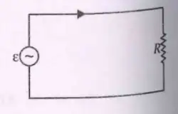
- Voltage: \( \varepsilon = \varepsilon_m \sin \omega t \)
- Current: \( I = I_m \sin \omega t \)
- Voltage and current are in phase (peaks coincide).
- Instantaneous power: \( P_r = I^2 R = I_m^2 R \sin^2 \omega t \)
- Average power over cycle: \( P = \langle P_r \rangle = \frac{1}{2} I_m^2 R = I_{rms}^2 R = \frac{\varepsilon_{rms}^2}{R} \)
Solved Examples
- Ex 1: Calculate average power if \( I_m = 4 \) A and \( R = 5 \) \( \Omega \).
- \( P = \frac{1}{2} \times 4^2 \times 5 = 40 \) W
- Ex 2: Find RMS voltage if \( \varepsilon_m = 220 \) V.
- \( \varepsilon_{rms} = 220 / \sqrt{2} = 155.56 \) V
Practice Set
- Q1: In a resistor, current and voltage are:
- A) Out of phase
- B) In phase
- C) 90° out of phase
- D) 180° out of phase
- Q2: Average power dissipated in resistor is:
- A) \( I_m^2 R \)
- B) \( \frac{1}{2} I_m^2 R \)
- C) \( I_{rms} R \)
- D) \( \varepsilon_m^2 / R \)
- Q3: If \( I_m = 6 \) A and \( R = 10 \) \( \Omega \), find average power.
- A) 180 W
- B) 360 W
- C) 720 W
- D) 60 W
Answer Key
- Q1: B - Current and voltage are in phase in resistor.
- Q2: B - Average power is \( \frac{1}{2} I_m^2 R \).
- Q3: A - \( P = \frac{1}{2} \times 6^2 \times 10 = 180 \) W.
Memory Aids
- In resistor, voltage and current peaks align.
- Average power = half of peak power.
Representation of AC Current and Voltage by Rotating Vectors–Phasors
Concepts
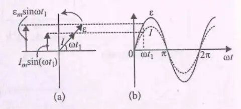
- Phasor: A vector rotating at angular speed \( \omega \) representing sinusoidal quantities.
- Voltage \( \varepsilon \) and current \( I \) in AC circuits are represented by phasors with magnitudes \( \varepsilon_m \) and \( I_m \).
- Vertical component of phasor gives instantaneous value: \( \varepsilon_m \sin \omega t \), \( I_m \sin \omega t \).
- Phasor diagram shows phase relationship; angle between voltage and current phasors is phase difference \( \phi \).
- For resistor-only circuit, voltage and current phasors are in phase (\( \phi = 0 \)).
Solved Examples
- Ex 1: In a resistor AC circuit, if \( \varepsilon_m = 10\,V \) and \( I_m = 2\,A \), find instantaneous voltage at \( \omega t = 30^\circ \).
- Use \( \varepsilon = \varepsilon_m \sin \omega t = 10 \times \sin 30^\circ = 10 \times 0.5 = 5\,V \).
- Ex 2: Find instantaneous current at \( \omega t = 60^\circ \) if \( I_m = 3\,A \).
- \( I = I_m \sin \omega t = 3 \times \sin 60^\circ = 3 \times 0.866 = 2.598\,A \).
Practice Set
- Q1: What does a phasor represent in AC circuits?
- A) Constant voltage
- B) Rotating vector representing sinusoidal quantity
- C) Direct current
- D) Resistance
- Q2: In a purely resistive AC circuit, the phase difference between voltage and current is:
- A) 90°
- B) 180°
- C) 0°
- D) 45°
- Q3: If the peak voltage is 20 V, what is the instantaneous voltage at \( \omega t = 45^\circ \)?
- A) 10 V
- B) 14.14 V
- C) 20 V
- D) 0 V
Answer Key
- Q1: B — Phasor is a rotating vector representing sinusoidal voltage or current.
- Q2: C — Voltage and current are in phase in a resistive circuit, so phase difference is 0°.
- Q3: B — Instantaneous voltage \( = 20 \times \sin 45^\circ = 20 \times 0.707 = 14.14\,V \).
Memory Aids
- Phasor = Rotating vector \( \rightarrow \) represents AC sinusoid.
- Resistor circuit: voltage and current phasors align (0° phase difference).
- Instantaneous value = peak × \( \sin \omega t \).
AC Voltage Applied to an Inductor
Voltage and Current Relationship
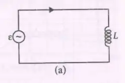
- Voltage across inductor: \( \varepsilon = \varepsilon_m \sin \omega t \)
- Current through inductor: \( I = I_m \sin (\omega t - \pi/2) \)
- Current lags voltage by \( \pi/2 \) radians (90°)
Current Amplitude
- Amplitude of current: \( I_m = \frac{\varepsilon_m}{\omega L} \)
- \( \omega = 2 \pi \nu \) (angular frequency in rad/s)
Inductive Reactance
- Inductive reactance: \( X_L = \omega L = 2 \pi \nu L \)
- Acts like resistance in AC circuit but depends on frequency and inductance
Solved Examples
- Ex 1: Find current amplitude if \( \varepsilon_m = 10\,V \), \( L = 0.5\,H \), \( \nu = 50\,Hz \).
- Calculate \( \omega = 2 \pi \times 50 = 314.16\,rad/s \)
- Calculate \( I_m = \frac{10}{314.16 \times 0.5} = 0.0637\,A \)
Practice Set
- Q1: What is the phase difference between voltage and current in a pure inductive circuit?
- A) 0
- B) \( \pi/4 \)
- C) \( \pi/2 \)
- D) \( \pi \)
- Q2: Inductive reactance \( X_L \) is given by:
- A) \( \frac{1}{\omega L} \)
- B) \( \omega L \)
- C) \( \frac{L}{\omega} \)
- D) \( \omega / L \)
- Q3: For an inductor of 0.2 H connected to 60 Hz AC supply, calculate \( X_L \).
- A) 75.4 \( \Omega \)
- B) 37.7 \( \Omega \)
- C) 12.56 \( \Omega \)
- D) 18.85 \( \Omega \)
Answer Key
- Q1: C) \( \pi/2 \) — Current lags voltage by 90° in pure inductance.
- Q2: B) \( \omega L \) — Inductive reactance is product of angular frequency and inductance.
- Q3: B) 75.4 \( \Omega \) — \( X_L = 2 \pi \times 60 \times 0.2 = 75.4 \Omega \).
Memory Aids
- Current lags voltage by 90° in inductors.
- Inductive reactance \( X_L = 2 \pi \nu L \).
- Higher frequency or inductance increases \( X_L \), reducing current amplitude.
Power in an Inductive Circuit
Instantaneous Power
- Instantaneous power: \( p_l = I \varepsilon = - \frac{I_m \varepsilon_m}{2} \sin (2 \omega t) \)
- Power oscillates sinusoidally, changing sign over time
Average Power
- Average power over one cycle: \( P_l = \langle p_l \rangle = 0 \)
- Because \( \langle \sin (2 \omega t) \rangle = 0 \)
- Inductor stores and returns energy; no net energy consumed
Solved Examples
- Ex 1: Calculate average power for \( I_m = 2\,A \), \( \varepsilon_m = 10\,V \).
- Use \( P_l = 0 \) for pure inductive load.
Practice Set
- Q1: What is the average power consumed by a pure inductor in AC circuit?
- A) Zero
- B) Maximum
- C) Half of maximum
- D) Depends on frequency
- Q2: Instantaneous power in an inductor is proportional to:
- A) \( \sin \omega t \)
- B) \( \sin 2 \omega t \)
- C) \( \cos \omega t \)
- D) Constant
- Q3: Why does average power in an inductor equal zero?
- A) No current flows
- B) Voltage and current are in phase
- C) Energy is stored and returned each cycle
- D) Resistance is zero
Answer Key
- Q1: A) Zero — Inductor does not dissipate energy, average power is zero.
- Q2: B) \( \sin 2 \omega t \) — Instantaneous power varies as \( \sin 2 \omega t \).
- Q3: C) Energy is stored and returned each cycle — No net energy loss.
Memory Aids
- Average power in pure inductors = 0.
- Instantaneous power oscillates at twice the supply frequency.
- Inductors store energy in magnetic field, return it to circuit.
Phasor and Waveform Representation
Phasor Diagram
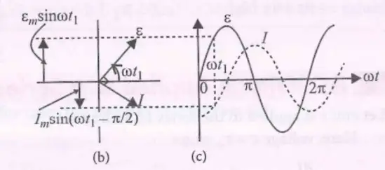
- Voltage and current represented as rotating vectors (phasors)
- Current phasor lags voltage phasor by \( \pi/2 \)
- Phasor length represents amplitude
Waveform Graphs
- Voltage: \( \varepsilon = \varepsilon_m \sin \omega t \)
- Current: \( I = I_m \sin (\omega t - \pi/2) \)
- Graphs show sinusoidal variation with phase difference
Solved Examples
- Ex 1: Identify phase difference from phasor diagram where current vector is perpendicular and behind voltage vector.
- Phase difference = \( \pi/2 \) lag of current.
Practice Set
- Q1: In phasor diagram, current vector lags voltage vector by:
- A) 0°
- B) 45°
- C) 90°
- D) 180°
- Q2: The waveform of current in an inductor is:
- A) In phase with voltage
- B) Leading voltage by 90°
- C) Lagging voltage by 90°
- D) Opposite phase to voltage
- Q3: Which graph correctly shows voltage and current in an inductive AC circuit?
- A) Both in phase
- B) Current leads voltage
- C) Current lags voltage by 90°
- D) Voltage lags current by 90°
Answer Key
- Q1: C) 90° — Current lags voltage by 90° in inductors.
- Q2: C) Lagging voltage by 90° — Characteristic of inductive load.
- Q3: C) Current lags voltage by 90° — Correct waveform relation.
Memory Aids
- Phasor current vector is 90° behind voltage vector in inductors.
- Waveform lag = \( \pi/2 \) radians or 90°.
- Voltage leads current in inductive circuits.
AC Voltage Applied to a Capacitor
Voltage and Current Relationship
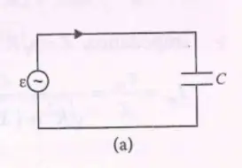
- Voltage across capacitor: \( \varepsilon = \varepsilon_m \sin \omega t \)
- Current through capacitor: \( I = I_m \sin (\omega t + \frac{\pi}{2}) \)
- Current leads voltage by \( \frac{\pi}{2} \) radians (90°)
- Peak current: \( I_m = \varepsilon_m \omega C \)
Capacitive Reactance
- Capacitive reactance: \( X_c = \frac{1}{\omega C} = \frac{1}{2 \pi \nu C} \)
- Acts like resistance opposing AC current
Power in Capacitor
- Instantaneous power: \( p_c = \frac{I_m \varepsilon_m}{2} \sin 2 \omega t \)
- Average power over a cycle: \( P_c = 0 \) (no net energy loss)
Solved Examples
Ex 1
- Given \( \varepsilon_m = 10\,V \), \( C = 5 \mu F \), \( \nu = 50\,Hz \)
- Calculate \( I_m \): \( I_m = \varepsilon_m \omega C = 10 \times 2\pi \times 50 \times 5 \times 10^{-6} = 0.0157\,A \)
Practice Set
Q1
In an AC circuit with a capacitor, the current leads the voltage by:
- A) 0
- B) \( \frac{\pi}{4} \)
- C) \( \frac{\pi}{2} \)
- D) \( \pi \)
Q2
Capacitive reactance \( X_c \) is given by:
- A) \( \omega C \)
- B) \( \frac{1}{\omega C} \)
- C) \( \omega L \)
- D) \( R \)
Q3
A capacitor of 10 \( \mu F \) is connected to 100 V AC of frequency 50 Hz. The capacitive reactance is:
- A) 318 \( \Omega \)
- B) 3180 \( \Omega \)
- C) 31.8 \( \Omega \)
- D) 3.18 \( \Omega \)
Answer Key
- Q1: C) \( \frac{\pi}{2} \) — Current leads voltage by 90° in capacitor.
- Q2: B) \( \frac{1}{\omega C} \) — Definition of capacitive reactance.
- Q3: A) 318 \( \Omega \) — \( X_c = \frac{1}{2\pi \times 50 \times 10 \times 10^{-6}} = 318 \Omega \).
Memory Aids
- Current leads voltage by 90° in capacitor.
- Capacitive reactance \( X_c = \frac{1}{2\pi \nu C} \).
- Average power in capacitor is zero.
Phasor Diagram and Waveform
Phasor Representation
- Phasors represent AC quantities as rotating vectors.
- Length = amplitude; angle = phase.
- Current phasor leads voltage phasor by \( 90^\circ \) in capacitor.
Waveform Graphs
- Voltage and current are sinusoidal waves.
- Current wave peaks before voltage wave by \( \frac{\pi}{2} \).
- Phase difference visible as time shift between peaks.
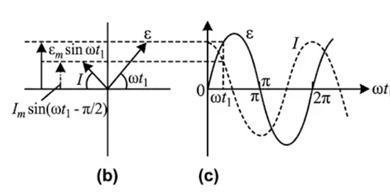
Solved Examples
Ex 1
- Given voltage \( \varepsilon = 10 \sin \omega t \), current leads by \( 90^\circ \)
- Current phasor at \( 90^\circ \) ahead of voltage phasor.
Practice Set
Q1
In a phasor diagram for a capacitor, the current vector is:
- A) In phase with voltage
- B) Lagging voltage by 90°
- C) Leading voltage by 90°
- D) Opposite to voltage
Q2
The phase difference between current and voltage in a capacitor is:
- A) 0°
- B) 45°
- C) 90°
- D) 180°
Q3
In waveform graphs, if current leads voltage by \( \frac{\pi}{2} \), the current wave peaks:
- A) At the same time as voltage
- B) After voltage
- C) Before voltage
- D) Never peaks
Answer Key
- Q1: C) Leading voltage by 90° — Current leads voltage in capacitor.
- Q2: C) 90° — Phase difference in capacitor.
- Q3: C) Before voltage — Current wave peaks earlier.
Memory Aids
- Phasor length = amplitude; angle = phase.
- Current phasor leads voltage by 90° in capacitor.
- Wave peak order shows phase lead/lag.
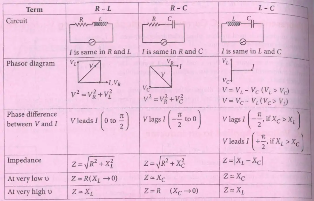
Combination of RL, RC and LC in AC Circuit
Basic Circuit Types
- R-L: Resistor and Inductor in series
- R-C: Resistor and Capacitor in series
- L-C: Inductor and Capacitor in series
Impedance and Phase
- R-L: \( Z = \sqrt{R^2 + (\omega L)^2} \), voltage leads current by \( \phi = \tan^{-1} \frac{\omega L}{R} \)
- R-C: \( Z = \sqrt{R^2 + \left(\frac{1}{\omega C}\right)^2} \), current leads voltage by \( \phi = \tan^{-1} \frac{1}{\omega CR} \)
- L-C: \( Z = |\omega L - \frac{1}{\omega C}| \), voltage and current phase depends on which reactance dominates
Frequency Behavior
- At low frequency, inductive reactance \( \omega L \) is small, capacitive reactance \( \frac{1}{\omega C} \) is large
- At high frequency, inductive reactance is large, capacitive reactance is small
- Circuits behave like dominant element at frequency extremes
Solved Examples
Ex 1
- R = 10 \( \Omega \), L = 0.1 H, \( \nu = 50 Hz \)
- Calculate impedance: \( Z = \sqrt{10^2 + (2\pi \times 50 \times 0.1)^2} = \sqrt{100 + 98.7} = 14.1 \ \Omega \)
Practice Set
Q1
In an R-L circuit, the phase angle \( \phi \) between voltage and current is:
- A) 0°
- B) Between 0° and 90° (voltage leads current)
- C) 90° (current leads voltage)
- D) 180°
Q2
In an R-C circuit, the impedance is:
- A) \( \sqrt{R^2 + (\omega L)^2} \)
- B) \( \sqrt{R^2 + \left(\frac{1}{\omega C}\right)^2} \)
- C) \( R + \omega L \)
- D) \( R + \frac{1}{\omega C} \)
Q3
In an L-C circuit, at resonance frequency \( \nu_0 \), the impedance is:
- A) Maximum
- B) Minimum (ideally zero)
- C) Equal to R
- D) Infinite
Answer Key
- Q1: B) Between 0° and 90° — Voltage leads current in R-L circuit.
- Q2: B) \( \sqrt{R^2 + \left(\frac{1}{\omega C}\right)^2} \) — Formula for R-C impedance.
- Q3: B) Minimum (ideally zero) — At resonance, inductive and capacitive reactances cancel.
Memory Aids
- R-L: Voltage leads current; impedance \( Z = \sqrt{R^2 + (\omega L)^2} \).
- R-C: Current leads voltage; impedance \( Z = \sqrt{R^2 + (1/\omega C)^2} \).
- L-C: Resonance when \( \omega L = 1/\omega C \), impedance minimum.
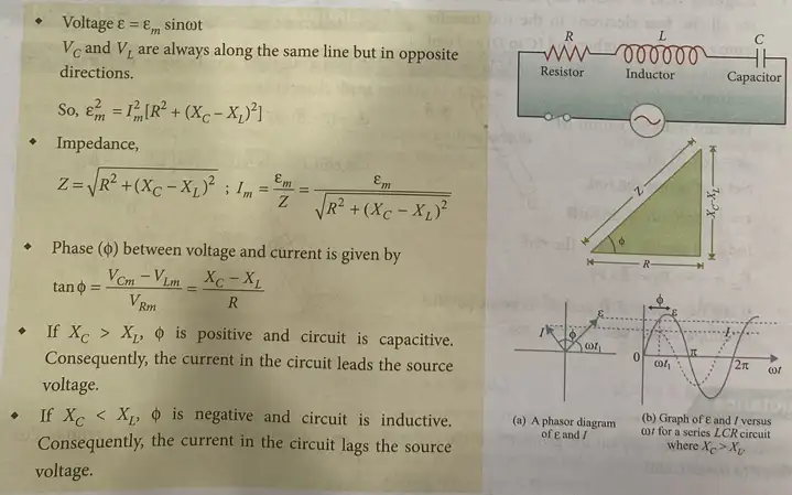
AC Voltage Applied to a Series LCR Circuit
Fundamentals
- Voltage applied: \( \varepsilon = \varepsilon_m \sin \omega t \)
- Voltage drops: \( V_R \) (resistor), \( V_L \) (inductor), \( V_C \) (capacitor)
- Voltages across capacitor and inductor are opposite in direction
- Total voltage relation: \( \varepsilon_m^2 = I_m^2 \left[R^2 + (X_C - X_L)^2 \right] \)
- Impedance: \( Z = \sqrt{R^2 + (X_C - X_L)^2} \)
- Current amplitude: \( I_m = \frac{\varepsilon_m}{Z} = \frac{\varepsilon_m}{\sqrt{R^2 + (X_C - X_L)^2}} \)
- Phase angle between voltage and current: \( \tan \phi = \frac{X_C - X_L}{R} \)
- If \( X_C > X_L \), circuit is capacitive; current leads voltage
- If \( X_C < X_L \), circuit is inductive; current lags voltage
Solved Examples
- Ex 1: Calculate impedance \( Z \) for \( R=10\Omega, X_C=30\Omega, X_L=20\Omega \).
- \( Z = \sqrt{10^2 + (30-20)^2} = \sqrt{100 + 100} = \sqrt{200} = 14.14\Omega \)
- Ex 2: Find current amplitude if \( \varepsilon_m = 100V \) and \( Z=14.14\Omega \).
- \( I_m = \frac{100}{14.14} = 7.07A \)
Practice Set
- Q1: In a series LCR circuit, if \( X_C = 40\Omega, X_L = 30\Omega, R = 10\Omega \), what is the impedance \( Z \)?
- A) 10 \( \Omega \)
- B) 20 \( \Omega \)
- C) 14.14 \( \Omega \)
- D) 50 \( \Omega \)
- Q2: For the above circuit, if \( \varepsilon_m = 100V \), what is the current amplitude \( I_m \)?
- A) 5 A
- B) 7.07 A
- C) 10 A
- D) 2.5 A
- Q3: If \( \tan \phi = 1 \) and \( R = 10\Omega \), what is \( X_C - X_L \)?
- A) 5 \( \Omega \)
- B) 10 \( \Omega \)
- C) 15 \( \Omega \)
- D) 20 \( \Omega \)
Answer Key
- Q1: C; \( Z = \sqrt{10^2 + (40-30)^2} = \sqrt{100 + 100} = 14.14\Omega \)
- Q2: B; \( I_m = \frac{100}{14.14} = 7.07A \)
- Q3: B; \( \tan \phi = \frac{X_C - X_L}{R} = 1 \Rightarrow X_C - X_L = R = 10\Omega \)
Memory Aids
- Impedance formula: \( Z = \sqrt{R^2 + (X_C - X_L)^2} \)
- Current amplitude: \( I_m = \varepsilon_m / Z \)
- Phase angle: \( \tan \phi = (X_C - X_L)/R \)
- Current leads if capacitive, lags if inductive
Resonance
Key Points
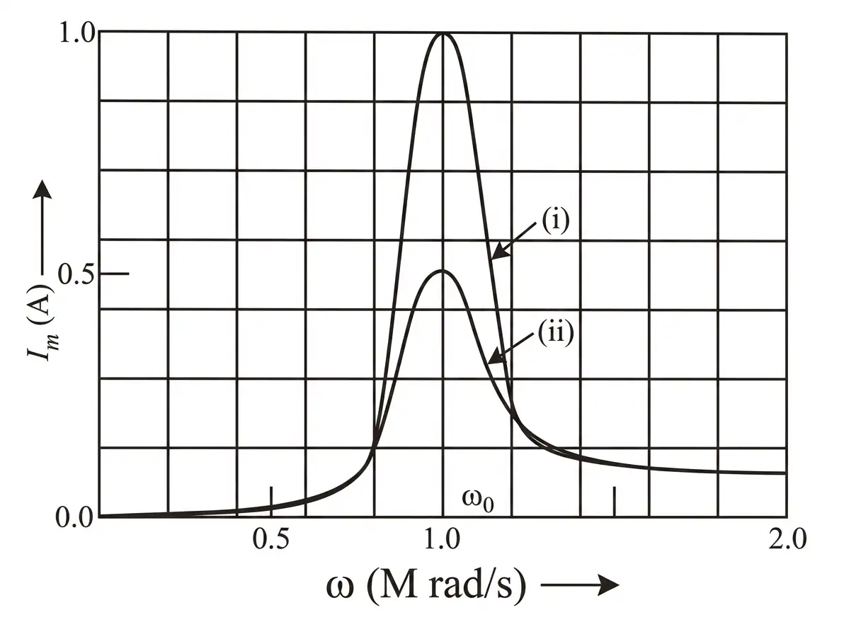
- Resonance occurs when inductive reactance equals capacitive reactance: \( X_L = X_C \)
- At resonance, impedance is minimum: \( Z = R \)
- Current amplitude at resonance: \( I_m = \frac{\varepsilon_m}{R} \)
- Resonant angular frequency: \( \omega_0 = \frac{1}{\sqrt{LC}} \)
- Resonant frequency: \( \nu_r = \frac{1}{2\pi \sqrt{LC}} \)
- Resonance does not occur in RL or RC circuits
- Higher resistance lowers peak current at resonance
Solved Examples
- Ex 1: Find resonant frequency for \( L=1mH, C=1nF \).
- \( \omega_0 = \frac{1}{\sqrt{1\times10^{-3} \times 1\times10^{-9}}} = 10^6 \text{ rad/s} \)
- \( \nu_r = \frac{1}{2\pi \times 10^{-6}} \approx 159 kHz \)
- Ex 2: Calculate current amplitude at resonance if \( \varepsilon_m=100V, R=100\Omega \).
- \( I_m = \frac{100}{100} = 1A \)
Practice Set
- Q1: At resonance, what is the impedance of a series LCR circuit?
- A) \( R \)
- B) \( X_L \)
- C) \( X_C \)
- D) \( 0 \)
- Q2: For \( L=2mH, C=0.5nF \), find resonant frequency \( \nu_r \).
- A) 159 kHz
- B) 159 MHz
- C) 225 kHz
- D) 225 MHz
- Q3: If \( R=50\Omega, \varepsilon_m=200V \), what is current amplitude at resonance?
- A) 2 A
- B) 4 A
- C) 0.25 A
- D) 1 A
Answer Key
- Q1: A; At resonance, \( Z=R \) as \( X_L = X_C \)
- Q2: B; \( \nu_r = \frac{1}{2\pi \sqrt{LC}} = \frac{1}{2\pi \sqrt{2\times10^{-3} \times 0.5\times10^{-9}}} \approx 159 \text{ MHz} \)
- Q3: A; \( I_m = \frac{\varepsilon_m}{R} = \frac{200}{50} = 4A \)
Memory Aids
- Resonance: \( X_L = X_C \)
- Minimum impedance: \( Z = R \)
- Resonant frequency: \( \nu_r = \frac{1}{2\pi \sqrt{LC}} \)
- Current max at resonance: \( I_m = \varepsilon_m / R \)
Quality Factor
Essentials
- Quality factor (Q) measures sharpness of resonance
- Defined as ratio of voltage across L or C to voltage across R at resonance
- Formulas:
- \( Q = \frac{\omega_0 L}{R} = \frac{1}{\omega_0 C R} = \frac{1}{R} \sqrt{\frac{L}{C}} \)
- Higher Q means better tuning and sharper resonance peak
Solved Examples
- Ex 1: Calculate Q for \( L=1mH, C=1nF, R=100\Omega, \omega_0=10^6 \text{ rad/s} \).
- \( Q = \frac{10^6 \times 1\times10^{-3}}{100} = 10 \)
- Ex 2: Find Q using \( Q = \frac{1}{R} \sqrt{\frac{L}{C}} \) with same values.
- \( Q = \frac{1}{100} \sqrt{\frac{1\times10^{-3}}{1\times10^{-9}}} = \frac{1}{100} \times 1000 = 10 \)
Practice Set
- Q1: For \( L=2mH, C=0.5nF, R=50\Omega, \omega_0=10^6 \text{ rad/s} \), find Q.
- A) 40
- B) 80
- C) 20
- D) 10
- Q2: Which of the following increases Q?
- A) Increase R
- B) Increase L
- C) Increase C
- D) Decrease L
- Q3: If Q = 50 and \( R=10\Omega \), what is \( \omega_0 L \)?
- A) 500
- B) 5
- C) 50
- D) 100
Answer Key
- Q1: B; \( Q = \frac{\omega_0 L}{R} = \frac{10^6 \times 2\times10^{-3}}{50} = 40 \)
- Q2: B; Increasing inductance \( L \) increases Q
- Q3: A; \( Q = \frac{\omega_0 L}{R} \Rightarrow \omega_0 L = Q \times R = 50 \times 10 = 500 \)
Memory Aids
- Q-factor: \( Q = \frac{\omega_0 L}{R} = \frac{1}{\omega_0 C R} = \frac{1}{R} \sqrt{\frac{L}{C}} \)
- Higher Q = sharper resonance
- Q inversely proportional to resistance
Power in AC Circuit: The Power Factor
Voltage and Current in AC Circuit
- Voltage: \( \varepsilon = \varepsilon_m \sin \omega t \)
- Current: \( I = I_m \sin (\omega t + \phi) \)
- Maximum current: \( I_m = \frac{\varepsilon_m}{Z} \)
- Phase angle: \( \phi = \tan^{-1} \left( \frac{X_C - X_L}{R} \right) \)
Instantaneous and Average Power
- Instantaneous power: \( p = \varepsilon I = \varepsilon_m I_m \sin \omega t \sin (\omega t + \phi) = \frac{\varepsilon_m I_m}{2} [\cos \phi - \cos (2\omega t + \phi)] \)
- Average power over a cycle: \( P = \langle p \rangle = \frac{\varepsilon_m I_m}{2} \cos \phi = \varepsilon_{rms} I_{rms} \cos \phi = I_{rms}^2 Z \cos \phi \)
- Power factor: \( \cos \phi \)
Types of Circuits and Power Factor
- Resistive circuit: Only resistance (R), \( \phi = 0 \), \( \cos \phi = 1 \), maximum power dissipation.
- Purely inductive or capacitive circuit: Phase difference \( \phi = \pi/2 \), \( \cos \phi = 0 \), no power dissipation (wattless current).
- LCR series circuit: Power dissipated only in resistor, \( \phi = \tan^{-1} \left( \frac{X_C - X_L}{R} \right) \).
- At resonance in LCR circuit: \( X_C = X_L = 0 \), \( \phi = 0 \), \( \cos \phi = 1 \), maximum power dissipated \( P = I_{rms}^2 R \).
Choke Coil
- Consists of an inductor with resistance \( R \).
- Used to reduce current without increasing power loss (e.g., tube lights).
- Impedance: \( Z = \sqrt{\omega^2 L^2 + R^2} \)
- Power factor: \( \cos \phi = \frac{R}{\sqrt{R^2 + \omega^2 L^2}} \approx \frac{R}{\omega L} \) (for \( R \ll \omega L \))
- Power absorbed is very small; current decreases without extra power loss.
Solved Examples
Ex 1
Calculate average power in an AC circuit with \( \varepsilon_m = 100\,V \), \( I_m = 5\,A \), and phase angle \( \phi = 30^\circ \).
- Use \( P = \frac{\varepsilon_m I_m}{2} \cos \phi \)
- \( P = \frac{100 \times 5}{2} \times \cos 30^\circ = 250 \times 0.866 = 216.5\,W \)
Ex 2
Find power factor of a choke coil with \( R = 10\,\Omega \), \( L = 0.1\,H \), and frequency \( f = 50\,Hz \).
- Angular frequency: \( \omega = 2\pi f = 314 \; rad/s \)
- \( \cos \phi = \frac{R}{\sqrt{R^2 + (\omega L)^2}} = \frac{10}{\sqrt{10^2 + (314 \times 0.1)^2}} = \frac{10}{\sqrt{100 + 985.96}} = \frac{10}{32.3} = 0.31 \)
Practice Set
Q1
In a purely resistive AC circuit, the power factor is:
- A) 0
- B) 0.5
- C) 1
- D) Depends on frequency
Q2
For an LCR circuit at resonance, the phase angle \( \phi \) is:
- A) 90°
- B) 0°
- C) 45°
- D) 180°
Q3
A choke coil has \( R = 5\,\Omega \), \( L = 0.2\,H \), and operates at \( 50\,Hz \). What is its power factor?
- A) 0.16
- B) 0.5
- C) 0.8
- D) 1
Answer Key
- Q1: C) 1 — In resistive circuits, voltage and current are in phase, so power factor is 1.
- Q2: B) 0° — At resonance, inductive and capacitive reactances cancel, phase angle is zero.
- Q3: A) 0.16 — \( \cos \phi = \frac{R}{\sqrt{R^2 + (\omega L)^2}} = \frac{5}{\sqrt{25 + (2\pi \times 50 \times 0.2)^2}} = 0.16 \)
Memory Aids
- Power factor \( = \cos \phi \), angle between voltage and current.
- Resistive circuit: power factor = 1 (max power).
- Pure inductive/capacitive: power factor = 0 (no real power).
- Choke coil reduces current with minimal power loss.
- At resonance, LCR circuit behaves like resistive circuit.
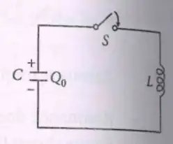
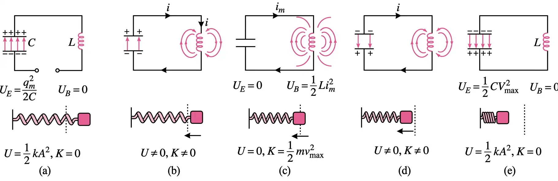
- LC circuit: capacitor (C) connected to inductor (L).
- Initially charged capacitor with charge \( Q_0 \).
- When switch closes, capacitor discharges, current builds magnetic field in inductor.
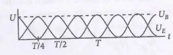
- Energy oscillates between electric field in capacitor and magnetic field in inductor.
- Magnetic energy: \( U_B = \frac{1}{2} L I^2 \), Electric energy: \( U_E = \frac{Q^2}{2C} \).
- Total energy constant: \( U = U_E + U_B = \text{constant} \).
- Energy conservation: \( \frac{dU}{dt} = 0 \)
- Governing equation: \( \frac{Q}{C} + L \frac{d^2 Q}{dt^2} = 0 \)
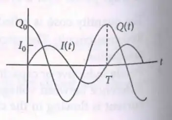
- Solution: \( Q(t) = Q_0 \cos (\omega_0 t + \phi) \), where \( \omega_0 = \frac{1}{\sqrt{LC}} \)
- Current: \( I(t) = -\frac{dQ}{dt} = I_0 \sin (\omega_0 t + \phi) \), \( I_0 = \omega_0 Q_0 \)
- Initial conditions: \( Q(0) = Q_0, I(0) = 0 \) imply \( \phi = 0 \)
- Electric energy: \( U_E = \frac{Q^2(t)}{2C} = \frac{Q_0^2}{2C} \cos^2 \omega_0 t \)
- Magnetic energy: \( U_B = \frac{1}{2} L I^2(t) = \frac{Q_0^2}{2C} \sin^2 \omega_0 t \)
- Total energy: \( U = U_E + U_B = \frac{Q_0^2}{2C} = \text{constant} \)
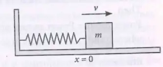
- LC oscillations analogous to spring-mass system oscillations.
- Energy oscillates between potential energy in spring and kinetic energy of mass.
- Both systems exhibit simple harmonic motion with energy conservation.
- \( \omega_0 = \frac{1}{\sqrt{LC}} = \frac{1}{\sqrt{0.5 \times 20 \times 10^{-6}}} = 316.2\,rad/s \)
- \( I_0 = \omega_0 Q_0 = 5000 \times 10^{-4} = 0.5\,A \)
- A) \( \frac{1}{2\pi \sqrt{LC}} \)
- B) \( \frac{1}{\sqrt{LC}} \)
- C) \( 2\pi \sqrt{LC} \)
- D) \( \sqrt{LC} \)
- A) Constant and oscillates between electric and magnetic forms
- B) Constant and stored only in capacitor
- C) Constant and stored only in inductor
- D) Decreases with time due to resistance
- A) 1000 rad/s
- B) 31622 rad/s
- C) 100000 rad/s
- D) 100 rad/s
- Q1: A) \( \frac{1}{2\pi \sqrt{LC}} \) — Frequency is inverse of period \( T = 2\pi \sqrt{LC} \).
- Q2: A) Constant and oscillates between electric and magnetic forms — Energy transfers between capacitor and inductor.
- Q3: B) 31622 rad/s — \( \omega_0 = \frac{1}{\sqrt{LC}} = \frac{1}{\sqrt{1 \times 10^{-3} \times 1 \times 10^{-6}}} = 31622 \)
- LC oscillation frequency: \( \omega_0 = \frac{1}{\sqrt{LC}} \)
- Energy oscillates between capacitor (electric) and inductor (magnetic).
- Current lags charge by 90° (sine vs cosine).
- LC circuit analogous to spring-mass SHM system.
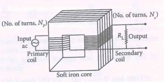
- Device converting low AC voltage to high AC voltage and vice versa.
- Operates on mutual induction principle.
- Ideal transformer relation: \( \frac{V_s}{V_p} = \frac{I_p}{I_s} = \frac{N_s}{N_p} = K \) (transformation ratio).
- Changing current in primary coil changes magnetic flux.
- Induces emf in secondary coil due to mutual induction.
- Ex 1: If \(N_p=100\), \(N_s=200\), and \(V_p=120\,V\), find \(V_s\).
- Use \( \frac{V_s}{V_p} = \frac{N_s}{N_p} \Rightarrow V_s = V_p \times \frac{N_s}{N_p} = 120 \times \frac{200}{100} = 240\,V \).
- Q1: Transformer works on the principle of:
- A) Electromagnetic induction
- B) Mutual induction
- C) Self induction
- D) Electrostatic induction
- Q2: For an ideal transformer, if \(N_s > N_p\), then it is a:
- A) Step-down transformer
- B) Step-up transformer
- C) Autotransformer
- D) None of these
- Q3: A transformer has 500 turns in primary and 100 turns in secondary. If primary voltage is 240 V, find secondary voltage.
- A) 48 V
- B) 1200 V
- C) 240 V
- D) 50 V
- Q1: B) Mutual induction - Transformer operates by emf induced in secondary coil due to changing flux from primary coil.
- Q2: B) Step-up transformer - \(N_s > N_p\) means voltage increases.
- Q3: A) 48 V - \(V_s = V_p \times \frac{N_s}{N_p} = 240 \times \frac{100}{500} = 48 V\).
- Transformation ratio \(K = \frac{N_s}{N_p} = \frac{V_s}{V_p} = \frac{I_p}{I_s}\).
- Step-up: \(N_s > N_p\), voltage increases.
- Step-down: \(N_s < N_p\), voltage decreases.
- Converts low AC voltage to high AC voltage.
- Primary coil voltage: \(V_p = -N_p \frac{d\phi}{dt}\).
- Secondary coil emf: \(\varepsilon_s = -N_s \frac{d\phi}{dt}\).
- Voltage ratio: \( \frac{V_s}{V_p} = \frac{N_s}{N_p} > 1 \).
- Power conservation: \(I_s V_s = I_p V_p\).
- Does not work with DC (no changing flux).
- Ex 1: Primary voltage = 100 V, \(N_p=50\), \(N_s=150\). Find secondary voltage.
- \(V_s = V_p \times \frac{N_s}{N_p} = 100 \times \frac{150}{50} = 300 V\).
- Q1: In a step-up transformer, the ratio \(\frac{N_s}{N_p}\) is:
- A) Less than 1
- B) Equal to 1
- C) Greater than 1
- D) Zero
- Q2: If primary voltage is 120 V and secondary voltage is 360 V, what is the turns ratio?
- A) 1:3
- B) 3:1
- C) 1:1
- D) 2:1
- Q3: Why transformers do not work on DC?
- A) No current flows
- B) No changing magnetic flux
- C) Resistance is too high
- D) Core saturates
- Q1: C) Greater than 1 - Step-up transformer increases voltage.
- Q2: A) 1:3 - \(\frac{V_s}{V_p} = \frac{N_s}{N_p} = \frac{360}{120} = 3\).
- Q3: B) No changing magnetic flux - DC produces constant flux, no emf induced.
- Step-up: \(N_s > N_p\), voltage increases.
- Voltage formula: \(V = -N \frac{d\phi}{dt}\).
- DC → no flux change → no emf.
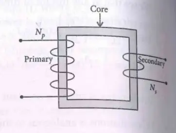
- Converts high AC voltage to low AC voltage.
- Turns ratio: \(N_s < N_p\), so \(V_s < V_p\).
- Voltage ratio: \( \frac{V_s}{V_p} = \frac{N_s}{N_p} < 1 \).
- Ideal transformer power: \(V_p I_p = V_s I_s\).
- Efficiency: \(\eta = \frac{P_{out}}{P_{in}} \times 100\% = \frac{V_s I_s}{V_p I_p} \times 100\%\).
- Energy losses include copper, hysteresis, eddy current, and flux losses.
- Ex 1: Primary voltage = 240 V, \(N_p=500\), \(N_s=100\). Find secondary voltage.
- \(V_s = 240 \times \frac{100}{500} = 48 V\).
- Ex 2: If output power is 480 W and input power is 500 W, find efficiency.
- \(\eta = \frac{480}{500} \times 100 = 96\%\).
- Q1: In a step-down transformer, the turns ratio \(\frac{N_s}{N_p}\) is:
- A) Greater than 1
- B) Equal to 1
- C) Less than 1
- D) Zero
- Q2: Efficiency of an ideal transformer is:
- A) 0%
- B) 50%
- C) 100%
- D) 75%
- Q3: Which loss is minimized by using laminated iron core?
- A) Copper loss
- B) Hysteresis loss
- C) Eddy current loss
- D) Flux loss
- Q1: C) Less than 1 - Step-down transformer reduces voltage.
- Q2: C) 100% - Ideal transformer has no energy loss.
- Q3: C) Eddy current loss - Laminated core reduces eddy currents.
- Step-down: \(N_s < N_p\), voltage decreases.
- Efficiency formula: \(\eta = \frac{V_s I_s}{V_p I_p} \times 100\%\).
- Losses: Copper (resistance), Hysteresis (magnetisation), Eddy currents (core), Flux leakage.
LC Oscillations
Basic Concept
Mathematical Description
Energy Oscillations
Mechanical Analogy
Solved Examples
Ex 1
Find the angular frequency \( \omega_0 \) of an LC circuit with \( L = 0.5\,H \) and \( C = 20\,\mu F \).
Ex 2
Calculate maximum current \( I_0 \) if maximum charge \( Q_0 = 10^{-4} C \) and \( \omega_0 = 5000\,rad/s \).
Practice Set
Q1
In an LC circuit, the frequency of oscillation is given by:
Q2
The total energy in an ideal LC circuit is:
Q3
For an LC circuit with \( L = 1\,mH \) and \( C = 1\,\mu F \), what is the angular frequency \( \omega_0 \)?
Answer Key
Memory Aids
Transformers
Overview
Principle
Solved Examples
Practice Set
Answer Key
Memory Aids
Step-up Transformer
Key Points
Solved Examples
Practice Set
Answer Key
Memory Aids
Step-down Transformer
Key Points
Solved Examples
Practice Set
Answer Key
Memory Aids
NEET Physics — ALL CHAPTERS
1
Basic Mathematics
2
Units and Measurement
3
Motion in a Straight Line
4
Motion in a Plane
5
Laws of Motion
6
Work, Energy and Power
7
System of Particles and Rotational Motion
8
Gravitation
9
Mechanical Properties of Solids
10
Mechanical Properties of Fluids
11
Thermal Properties of Matter
12
Thermodynamics
13
Kinetic Theory
14
Oscillations
15
Waves
16
Electric Charges and Fields
17
Electrostatic Potential and Capacitance
18
Current Electricity
19
Moving Charges and Magnetism
20
Magnetism and Matter
21
Electromagnetic Induction
22
Alternating Current
23
Electromagnetic Waves
24
Ray Optics and Optical Instruments
25
Wave Optics
26
Dual Nature of Radiation and Matter
27
Atoms
28
Nuclei
29
Semiconductor Electronics: Materials, Devices and Simple Circuits